Hindsight brings perspective to any broadcast installation, particularly when we look back at the unique challenges of the recent repack. A Phase 5 project for MyTV affiliate WRDC-TV and CW affiliate WLFL-TV was no exception as we navigated the deadline-driven pressures of this particularly active phase.
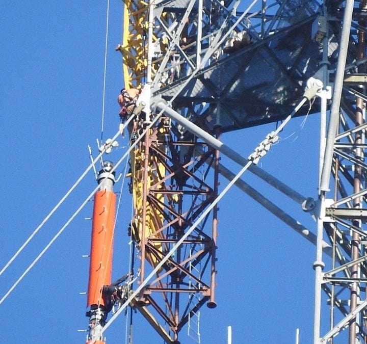
Both stations transmit to the Raleigh-Durham market from atop a candelabra tower, which has six top-mounted antenna positions with exceptional sightlines. To maximize signal coverage and reduce weight, we opted for a stacked omnidirectional UHF antenna system from Dielectric that would serve WRDC’s Channel 14 assignment and WLFL’s Channel 18 assignment.
The omnidirectional coverage is necessary due to the market’s size and terrain. Since the antennas are stacked, both transmit into free space as true top-mounted arrays that do not interfere with each other. In a typical stack, the bottom array becomes directional due to the effect of the transmission line feeding the top antenna. Both the horizontal and vertical azimuth patterns are affected, with the vertical seeing more negative impact.
The Dielectric engineering team overcame this drawback with an innovative design that results in the bottom of the stack being as omnidirectional in both polarizations as the top. This is a significant engineering breakthrough that assures WLFL will not suffer from interference issues.
The design includes plenty of vertical polarization to enhance signal reception through the region’s rolling hills and valleys. Both stations broadcast NextGen TV content today, and that vertical signal component will increase in importance as more viewers consume NextGen TV content on mobile devices.
We scheduled a helicopter lift to raise the stacked antenna system, with WRDC’s center of radiation (1,950 feet) roughly 60 feet above WLFL’s (1,888 feet). A temporary Dielectric TFU-WB side-mounted antenna continued on-air operations while the old antennas were removed. The stacked system, which comprises two Dielectric slot antennas, positions WRDC’s more compact custom 27-bay TFU-ETT antenna atop the larger 26-bay TFU-JBH structure.
The new antennas are each fed by 7-3/16” Dielectric transmission line runs, with one newly installed digiTLine run. The post-installation RF sweeps confirmed that both overall system VSWR results were excellent, comfortably bettering our minimum requirements and enabling the transmitters to run at optimum efficiency.
A NEW KIND OF FILTER
This system requires an unusually complex filter design for WRDC since it operates on Channel 14. A typical UHF transmission system requires a six- or eight-pole filter to reduce out-of-band emissions to meet FCC specifications. Channel 14 is unique in that it requires a very steep roll-off at the lower side band to prevent interference into land mobile frequencies just below the band edge.
Dielectric engineered a very sharp-tuned 12-pole filter to eliminate out-of-band emissions from WRDC’s (Channel 14) 108 kW transmitter. While the 12-pole design creates a larger physical footprint, we worked closely with Acrodyne Services to ensure a clean installation in a tight space, including temporary use of their 20 kW MAT (Mobile Acrodyne Transmitter) outside the building to facilitate new equipment placement inside. The filter was floor-mounted alongside WRDC’s six-cabinet transmitter, WLFL’s four-cabinet transmitter and filter, a dual-channel combiner and all associated plumbing and switching systems.
Moving forward, we plan to install Dielectric’s RFHAWKEYE to monitor antenna and RF performance for both stations over IP. That will add a new level of operational efficiency for our Raleigh-Durham engineering team, especially as we put more emphasis on ATSC 3.0 and NextGen TV signals in the years ahead.
Dale Scherbring is the director of engineering for WRDC-TV and WLFL-TV. He can be reached at 410-487-3492.
For more information, please contact Jay Martin at Dielectric at 207-655-8138, or visit the company’s website at www.dielectric.com.


